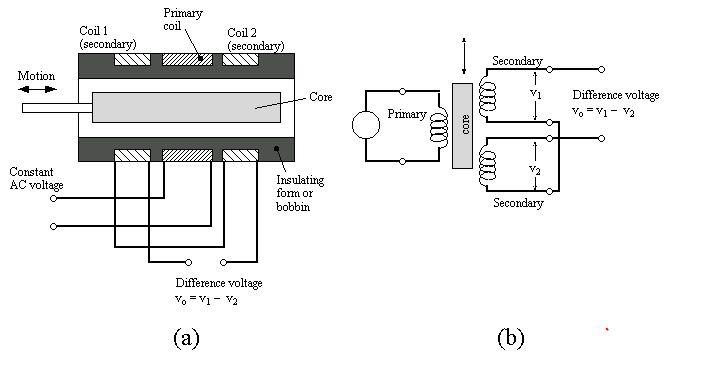
Linear Variable Differential Transformer
Principle
The basic diagram of LVDT is having single primary winding and two secondary windings A and B wound on a cylindrical former. The secondary winding have equal number of turns and are identically placed on either side of the primary winding. The primary winding is connected to an alternating current source. A movable soft iron core is placed inside the former. The displacement to be measured is applied to the attachments to the soft iron core.
Since the primary winding is excited by an alternating current source, it produces an alternating magnetic field which in turn induces alternating current in two secondary windings.
The out put voltage of secondary, A, is Va and that of B, is Vb. In order to convert the outputs from Va and Vb into single voltage signal, the two secondaries are connected in series opposition. Thus the output voltage of the transducer is the difference of the two voltages.
Differential output voltage,
Vo=Va-Vb
Working
When the core is its normal position , the flux linkage with both the secondary windings is equal and hence emf are induced in them.Thus at null position Va=Vb
Since the out put voltage of the transducer is the difference of two voltages, the out put voltage Vo is zero at null position.
Now if the core is moved to left of the null position, more flux links with winding A and less with winding B. Accordingly out put voltage Va, of the secondary winding A, is more than Vb,the out put voltage is in phase with the primary voltage. Similarly, if the core is moved to the right of the null position, the flux lining with winding B becomes larger than linking with A. This results in Vb larger than Va
The out voltage in this case is
Vo = Vb - Va
and is 180oout of phase with primary voltage. Therefore, the two differential voltages are out of phase by 180o with each other
The amount of voltage change in either secondary windings is proportional to the amount of movement of the core. Hence, we have an indication of amount of linear motion. By noting which output voltage is increasing or decreasing, we can determine the direction of motion. In other words any physical displacement of core causes the voltage in the secondary winding to increase while simultaneously reducing the voltage in other secondary winding. The difference of two voltage appear across the output terminals of the transducer and gives a measure of physical position of core and hence the displacement.
As the core is moved in one direction from the null position, the differential voltage or the difference of the two secondary voltages, will increase while maintaining an in phase relationship with the voltage from the input source. In the other direction from null position, the differential voltage will also increase, but will be 180o out of phase with the voltage from the source. By comparing the magnitude and phase of output voltage with the voltage with that of the the source, the amount and direction of the movement of the core and hence of displacement may be determined
The amount of output voltage may be measured to determine the displacement. The output signal may also be applied to a recorder or to a controller that can restore the moving system to its normal position
Features of LVDT
1.High range
2.Friction and Electrical isolation
3.Immunity from External Effects
4.High input and high sensitivity
5.Low hysteresis
No comments:
Post a Comment